Overview
The Command Buffer input mode (Digital Inputs and Outputs) allows you to change values for parameters using a digital input.
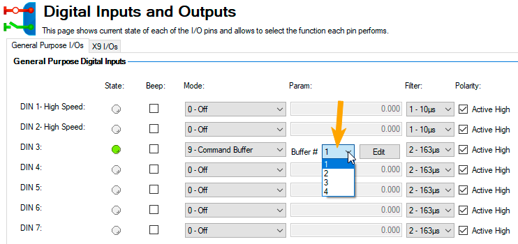
The drive has four available buffers. A digital input configured for command buffer mode is linked to one command buffer set. This is determined by the user (see arrow 1). In this case, command buffer 1 is used.
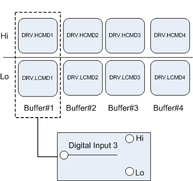
The graphic below explains the architecture of the buffers.
Available buffers in AKD:
Editing the Command Buffers
By default, the buffers are empty. Each side of the buffer can contain 128 characters maximum (parameter and value included). You can use the Command Buffer Editor to enter the sequence of commands to the digital input buffer. You can enter the sequence of commands into Low command buffer (DIN.LCMDx) or High command buffer (DIN.HCMDx) and save these settings to the drive.
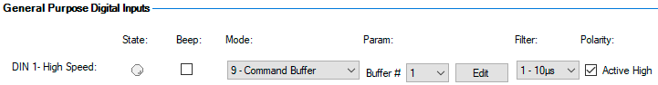
To edit the command buffers, open the Digital I/O view and select Digital input mode as 9 – Command Buffer.
The Param box lists the available command buffers. Select desired command buffer number for the DIN. This number sets to the DINx.PARAM keyword. When you mouse over the Param box, the Tooltip displays the current content of the High command buffer and Low command buffer in the drive.
To edit the selected command buffer, click Edit to display the command buffer editor screen.
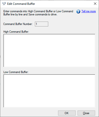
The command buffer editor screen has following properties:
| Button or Dialog Box | Description |
|---|---|
|
Command Buffer Number |
The identification number of the command buffer (1, 2, 3, 4). |
|
High Command Buffer |
Adds sequence of commands to the High command buffer parameter. Contents are saved to the keyword DIN.HCMDx. A maximum of 128 characters can be set to drive along with the separator “;”. Commands must be entered line by line and when saving to the drive each commands will be formed into single line separated by “;”. |
|
Low Command Buffer |
Adds sequence of commands to the Low command buffer parameter. Contents are saved to the keyword DIN.LCMDx. A maximum of 128 characters can be set to drive along with the separator “;”. Commands must be entered line by line and when saving to the drive each commands will be formed into single line separated by “;”. |
|
Ok |
Saves the sequence of commands to the drive. |
|
Close |
Closes the screen and returns to Digital I/O view. If contents are not saved to drive before closing the screen, confirmation message “The commands have been modified and not save to drive. Do you want close without saving?” is displayed. |
Commands and parameters are entered on separate lines with a space between the parameter and the value.
A semicolon separator is not necessary in the editor, but it is required if the buffers are edited inside the terminal window.
Behavior of the Command Buffer
Digital inputs have either a high or a low state. The contents of the buffer are executed at the rising edge of the state change. The contents of the buffer are also loaded at drive power up according to the starting state of the digital input. When the command buffer is initially configured, the buffer is not executed until the first digital input state change is detected.
Tip: Once you have the buffer configured and tested, put the digital input in the most common state that it will be in at start up. Save the parameters to the drive. This will synchronize the NVRAM with the buffer, so at start up, values will not have to be changed.
Delays for the Buffer
There is a delay command that can be used to delay the execution of a command or parameter change (DRV.CMDDELAY). The value can be from 0 ms to 5000 ms.
The following commands may require a delay before the next command in the buffer can be executed:
DRV.EN (100 ms min)
DRV.DIS (50 ms min)
Example:
DRV.EN
DRV.CMDDELAY 100
MT.MOVE
The command buffer does not send back warnings when a parameter is invalid or out of range, so make sure the syntax is correct and that the digital input changes during legal drive states for the commands given.